Prompted by megatrends such as climate change, the energy transition, and the general increase in electrification of daily life, the number of electronic devices and machines around us continues to grow. Electric bicycles, electric scooters and even electric surfboards, but above all the electrification of the car, are bringing the topic of e-mobility to the fore.
All of these applications require efficient and reliable electric motors. Elementary components of electric motors are the rotor and stator. But what tasks do the rotors and stators perform in electric machines, how do they work and how are they manufactured?
To be able to go into this question in more detail, we first have to deal with how an electric motor basically works.
Most electric motors are based on the principle of the so-called Lorenz force. It is a force acting on a current-carrying conductor in the external magnetic field.
If the direction of the current in the conductor changes with a certain frequency, the movement of the conductor is caused in the magnetic field. Due to the special design of an electric motor, the alternating current generates a rotary motion that can be used as a drive.
In order for the magnetic field to be generated and conducted in a specific way, ferromagnetic materials are used. These include iron, nickel, cobalt, as well as certain alloys and non-metallic compounds (soft ferrites, many permanent magnets).
Some electric motors use the so-called reluctance force to generate the torque in the rotor. Here, the motion comes from the system striving for minimum magnetic resistance (reluctance). The ferromagnetic, or more precisely the soft magnetic materials are also used for these motors.
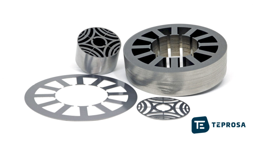
The rotor is the moving, or rather rotating part of the electric motor. The rotor sits between the poles of the stator. It is often made of iron or iron alloy and therefore also called iron core or magnetic core.
Since an iron core made of solid material is inefficient in terms of performance due to high eddy current losses, a rotor is made of individual laminations, also called rotor lamellas. This also applies to the stator laminations. The stator and rotor laminations are punched from electrical sheets or cut on the laser cutting machine, stacked to form magnetic cores, joined together (e.g., glued, welded, riveted, etc.) and fitted with windings (stator) or with permanent magnets (rotor). Depending on the design of the electric motor, both the rotor and the stator can be provided with permanent magnets or with windings.
Modern drive motors can reach speeds of 10,000 rpm and even considerably higher. This generates considerable centrifugal forces in the rotor. For the positioning and alignment of the magnets in the rotor, corresponding openings known as magnet pockets are used.
In the magnetic pockets, the sensitive (brittle) magnets are safely protected from the high centrifugal forces.
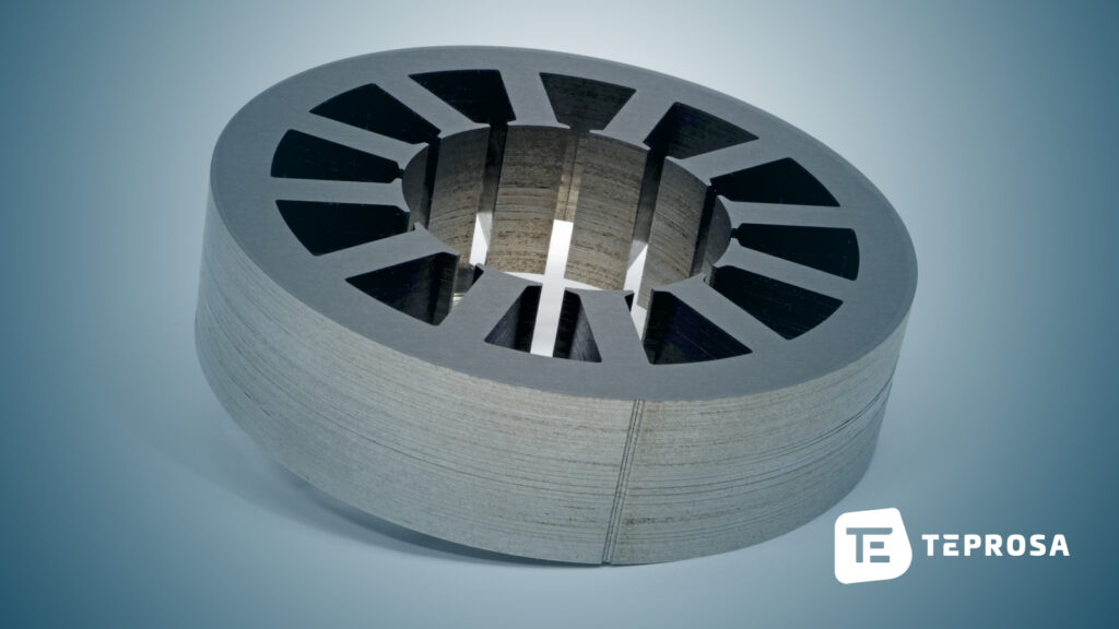
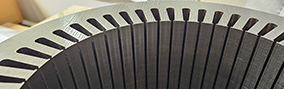
Statorpaket-Blechpaket-Elektroblech-TEPROSA
The stator, also called the stator, is the immobile part of the electric motor and the magnetic counterpart of the rotor. Its function is to guide the magnetic field within the electric motor.
Stators can be equipped with permanent magnets as well as electromagnets. The rotor rotates in the stator, or between the magnetic north and south poles of the stator. One speaks of an internal rotor when the stator is firmly connected to the outer housing of the electric motor and the rotor rotates in the bore of the stator. In contrast, an electric motor is called an external rotor when the stationary part (stator) of the machines is inside it and is enclosed by the moving part (rotor or armature).
.
Rotor and stator are usually constructed and manufactured in the so-called laminated construction. This is referred to as the laminated construction method because the magnetic cores (rotor core, stator core) are made of individual metal sheets, also known as sheet laminations, each of which is insulated from the other by a coating a few micrometers thick.
The individual sheets are stacked on top of each other and baked or screwed together to form a sheet stack. A stack of laminations represents a magnetic core and thus a rotor or stator.
Electrical steel strip is used to manufacture the individual laminations of rotors and stators. Electrical steel strip or electrical sheet is an iron-silicon alloy with special magnetic properties that are particularly suitable for use in electric motors and generators.
Due to these special properties, the use of laminations made of electrical steel in the manufacture of rotors and stators contributes to significantly improved energy efficiency (efficiency) of electrical systems and thus to sustainable and optimal use of the required energy.
The electrical steel used for laminated core consists of an iron-silicon alloy and is basically classified into two types: isotropic or non-grain-oriented and anisotropic or grain-oriented electrical steel.
The magnetic properties of isotropic electrical steel are largely uniform and therefore almost independent of the direction of magnetization. This isotropy arises due to a non-ordered distribution of the location of iron elementary cells in the electrical steel.
Homogeneity of magnetic properties is important for all rotating machines, such as electric motors or generators. Minor inhomogeneities (anisotropies), which are unavoidable in the manufacturing process of electrical steel, can be compensated by using special technologies in the construction of electrical machines.
Sheet packages for motors in the form of stator (also called stator) and rotor are made of layered individual laminations of electrical steel insulated from each other. The laminations usually have a material thickness of between 0.10 and 1.00 mm, with the most common thicknesses of 0.35 mm and 0.50 mm establishing themselves as the standard.
Insulation between the sheets is achieved by a specific coating that prevents electrical contact between the individual sheets. These coatings often have a thickness of only a few micrometers.
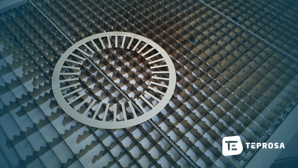
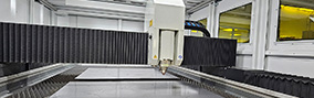
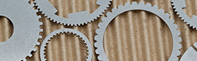
Electric sheet lamination for stator sheet laser cutting TEPROSA
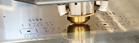
The individual laminations are stamped or laser cut, with the stamping process being suitable for high-volume production and laser cutting offering flexibility for prototyping and small- and medium-scale production.
Laser cutting also has several other specific advantages over punching, for example, virtually no structural changes occur at the edges of the individual layers during laser cutting compared with punching. The individual sheets are then firmly joined together. With punching, this step already takes place in the punching tool.
This is also referred to as punch packaging. Laser-cut lamellae are precisely aligned with a corresponding device, stacked on top of each other and glued (adhesive packaging) or baked (baked enamel process).
Both the baked varnish process and adhesive stacking result in complete insulation of the individual sheets and prevent possible short circuits between the laminations, which can cause an increase in eddy current losses. The full-surface bonding of the layers also suppresses unwanted vibrations.
TEPROSA relies on laser cutting of the sheet and packaging of the packages using the baked enamel process. The magnetic cores we manufacture in this way are free of short circuits and have ideal magnetic properties due to the gentle manufacturing process.
To prevent the short circuits between the laminations in electrical laminations and thereby reduce the eddy currents, various coatings are applied to the strip.
The coating thicknesses vary from 1 to 4 µm. Depending on the processing technology and subsequent application, coatings exist for better corrosion protection, improved insulation of the individual layers, heat resistance, improved punching properties or weldability.
TEPROSA GmbH specializes for many years in the manufacture of rotors and stators for electric motors with exceptionally high quality. In the field of electrical steel sheets, we manufacture for you individual laminations for stator and rotor, as well as complete sheet packages (stator- or rotor packages) from different electrical steel grades.
We process grain oriented electrical steel for generators, transformers and other electrical machinery. We rely on baked enamel technology for the packaging of the individual laminations. Alternatives are welding or bolting of laminated cores.
As a long-standing supplier to various OEMs, the quality of our work is particularly important to us. Therefore, we work according to standardized processes and thus ensure consistent quality and complete traceability of each individual manufacturing step.

TEPROSA GmbH, Paul-Ecke-Strasse 6, 39114 Magdeburg, Germany
Geschäftsführer & Gesellschafter der TEPROSA GmbH.
Paul-Ecke-Str. 6
39114 Magdeburg
Deutschland

