![]()
Laser cutting is an innovative cutting process that enables uncompromising precision. The process is therefore used whenever millimeters matter. How the process works in detail, what advantages & possibilities it offers, we have summarized in this overview.
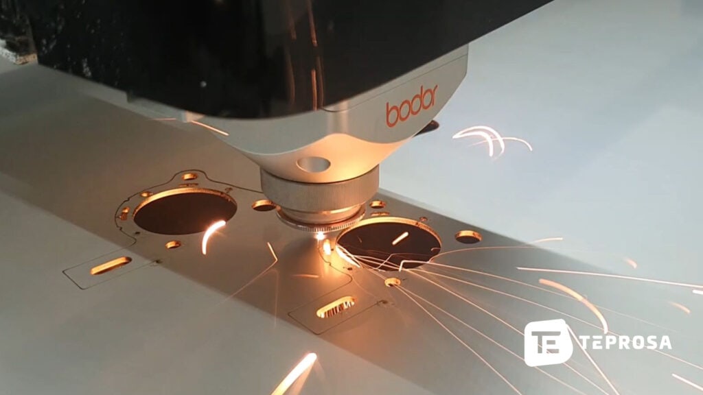
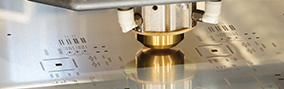
Laser cutting, along with plasma and oxyfuel cutting, is one of the thermal cutting processes. When cutting with a laser, light is bundled into a beam via a so-called beam guide/cutting nozzle and the processing head (focusing optics) and thus directed as a strongly focused laser beam onto the material surface of the workpiece to be processed.
The material is heated by the laser beam to such an extent that it melts or vaporizes. The resulting vapors and melt are then expelled with a process gas. In fiber lasers (special type of solid-state laser), a laser beam in the mid-infrared range with a wavelength of 1,064 nm is generated in the laser beam source and amplified via an elongated fiber.
Laser cutting is divided into laser flame cutting, laser fusion cutting and laser sublimation cutting. Depending on the laser process, different process gases are used to assist or enhance the cutting process. The basic principle of all processes used in laser cutting with the fiber laser is identical. Nevertheless, each process has very special properties.
In laser fusion cutting, the material is melted by a focused laser beam and blown out of the kerf by the cutting gas used. Fusion cutting (also known as laser cutting) is the preferred cutting process for machining stainless steel and various aluminum alloys.
The process gas, usually nitrogen, protects the cut edge from unwanted oxidation due to its low-reaction properties (inert gas). This is also referred to as bright cutting.
The thermal input on the laser medium is rather low. This results in clean, virtually burr-free cut edges and laser parts with almost no distortion or burr. Post-processing of the parts produced in this way is often not necessary.
In laser flame cutting (also known as laser beam cutting), oxygen is used as the cutting gas. The material to be cut is heated by the laser beam in the first step. In the second step, the cutting gas is blown into the kerf and the material is burned by the supporting effect of the oxygen.
The oxygen fulfills two functions, it reacts with the previously heated material and removes the liquid oxide from the kerf.
Due to the chemical reaction, laser flame cutting results in a small amount of burr formation on the cutting edges, which must be subsequently removed in the case of thicker films.
In laser sublimation cutting, the material to be processed vaporizes immediately as a result of processing with the laser beam. The resulting vapor is then blown out by the cutting gas, usually nitrogen. In sublimation cutting, there is no burr on the edges.
These materials are suitable for laser cutting:
| designation | Material grade | Note |
|---|---|---|
| Mild steel | 1.0330, DC01 1.0338, DC04 |
unalloyed quality steels |
| C steel/ carbon steel | 1.1274, C100S C75S |
Spring strip steel without corrosion resistance, magnetic |
| Stainless steel V2A | 1.4301 1.4316 |
Stainless, austenitic standard stainless steels |
| Stainless steel V4A | 1.4404 | Corrosion, acid and high temperature corrosion resistant stainless steels |
| Spring steel | 1.4310 | Rust-free, good corrosion resistant, austenitic spring steels |
| Stainless steel | 1.4828 | Standard austenitic stainless steels |
| Stainless steel | 1.4016 | non-rusting, ferritic steel magnetic |
| designation | Material grade | Note |
|---|---|---|
| Aluminum | AW-5754 (AlMg3), AW-1050A (pure aluminum), AW 6082 (AlSi1MgMn) |
Lightweight, relatively soft material, corrosion resistant, good formability and weldability |
| Titanium | Ti | Lightweight, passivatable and biocompatible material, frequent use in medical technology |
| designation | Material grade | Note |
|---|---|---|
| Bronze | CW452K | Resistant to corrosion and wear, high strength and hardness |
| Copper | CW004A, CW008A, CW024A |
good electrical conductivity, corrosion resistant, good cold and hot formability, suitable for brazing and soldering |
| copper-nickel | Very corrosion resistant, well weldable |
|
| brass | CW508L, CW612N | Good electrical conductivity, good cold formability, good spring properties |
| Nickel | Nickel, MU metal | Extremely corrosion resistant, ferromagnetic properties |
| designation | Material grade | Note |
|---|---|---|
| Silicon nitride | Si3N4 | extremely loadable, high temperature stability, very high thermal shock resistance |
As with any cutting process, minor deviations from the production data also occur during laser cutting due to the production process. These are caused, for example, by minute inaccuracies in the movement of the laser system, irregularities in the material and in beam shaping.
To ensure that the laser parts nevertheless meet their requirements, fit accurately and, above all, are interchangeable in series production or mass production, permissible tolerances to the nominal dimension are determined. By specifying suitable manufacturing tolerances, the desired accuracy of a cutting part can be clearly defined, necessary clearance or overfitting between two parts can be specified, and the economic efficiency of production can also be optimized. Here, the tolerance results from the difference between the maximum dimension and the minimum dimension.
The tolerance is therefore the permissible deviation of the blank from the nominal dimension, which the customer specifies to the manufacturer. The actual dimension of the laser-cut part must lie within the upper and lower limit dimensions. If no explicit specifications are determined by the customer, standards exist for general manufacturing tolerances.
DIN ISO 2768 summarizes generally applicable tolerance dimensions that are used on many technical drawings for tolerancing dimensions and angles that are not separately toleranced. That is, for dimensions that do not have an explicit specification for the nominal dimension and the permissible tolerance.
Within DIN ISO 2768, there are so-called tolerance classes that define tolerances of varying closeness. The general tolerances are subdivided as follows:
At TEPROSA, all cutting parts are manufactured according to the standard DIN ISO 2768-1 m (general tolerances) for the geometric dimension, unless otherwise agreed with the customer. Through the four possible tolerance classes fine (f), medium (m), coarse (g) and very coarse (sg), the respective accuracy in manufacturing is defined and simplified by DIN ISO 2768-1.
| Tolerance class |
Limit dimensions in mm for nominal dimension range in mm | |||||||||
| < 0.5 | 0.5 to 3 | about 3 to 6 | over 6 to 30 | over 30 to 120 | over 120 to 400 | over 400 to 1000 | over 1000 to 2000 | over 2000 to 4000 | over 4000 to 8000 | |
| f (fine) | ± 0.05 | ± 0.05 | ± 0.10 | ± 0.15 | ± 0.2 | ± 0.3 | ± 0.5 | – | – | |
| m (medium) | ± 0.10 | ± 0.10 | ± 0.20 | ± 0.30 | ± 0.5 | ± 0.8 | ± 1.2 | ± 2 | ± 3 | |
| Tolerance-. Class |
Limit dimensions in mm for nominal dimension range in mm | |||||
| < 0.5 | 0.5 to 3 | about 3 to 6 | over 6 to 30 | over 30 to 120 | over 120 to 400 | |
| f (fine) | ± 0.2 | ± 0.5 | ± 1.0 | ± 2.0 | ± 4.0 | |
| m (medium) | ± 0.4 | ± 1.0 | ± 2.0 | ± 4.0 | ± 8.0 | |
In terms of straightness or flatness, DIN ISO 2768-2 recognizes the tolerance classes H, K and L.
| Tolerance-. Class |
General tolerances for straightness and flatness in mm for nominal dimension range mm | |||
| up to 100 | over 100 up to 300 |
over 300 up to 1000 |
over 1000 up to 3000 |
|
| H | 0.2 | 0.3 | 0.4 | 0.5 |
| K | 0.4 | 0.6 | 0.8 | 1 |
| L | 0.6 | 1 | 1.5 | 2 |
DIN EN ISO 9013 defines standard tolerances for thermal processes. In addition to laser cutting, the plasma cutting and oxyfuel cutting processes are mentioned. DIN EN ISO 9013-1 is another standard that defines relevant specifications for laser flame cutting with regard to tolerances.
| workpiece thickness | Nominal dimensions | |||||||||
| > 0 to | ≤ 3 to | ≤ 10 to | ≥ 35 to | ≥ 125 to | ≥ 315 to | ≥ 1,000 to | ≥ 2,000 to | ≥ 4,000 to | ≥ 6,000 to | |
| < 3 | < 10 | < 35 | < 125 | < 315 | < 1,000 | < 2,000 | < 4,000 | < 6,000 | < 8,000 | |
| Limit dimensions | ||||||||||
| > 0 to ≤ 1 | ± 0.075 | ± 0.1 | ± 0.1 | ± 0.2 | ± 0.2 | ± 0.3 | ± 0.4 | ± 0.65 | ± 0.9 | ± 1.6 |
| > 1 to ≤ 3.15 | ± 0.1 | ± 0.1 | ± 0.2 | ± 0.25 | ± 0.25 | ± 0.35 | ± 0.4 | ± 0.65 | ± 1 | ± 1.75 |
| > 3.15 to ≤ 6.3 | ± 0.2 | ± 0.2 | ± 0.25 | ± 0.25 | ± 0.3 | ± 0.4 | ± 0.45 | ± 0.7 | ± 1.1 | ± 1.9 |
| > 6.3 to ≤ 10 | – | ± 0.25 | ± 0.3 | ± 0.3 | ± 0.35 | ± 0.45 | ± 0.55 | ± 0.75 | ± 1.25 | ± 2.2 |
| > 10 to ≤ 15 | – | ± 0.3 | ± 0.35 | ± 0.4 | ± 0.45 | ± 0.55 | ± 0.65 | ± 0.85 | ± 1.5 | ± 2.5 |
| > 15 to ≤ 20 | – | ± 0.4 | ± 0.4 | ± 0.45 | ± 0.55 | ± 0.75 | ± 0.85 | ± 1.2 | ± 1.9 | ± 2.8 |
| > 20 to ≤ 25 | – | ± 0.45 | ± 0.5 | ± 0.6 | ± 0.7 | ± 0.9 | ± 1.1 | ± 1.6 | ± 2.4 | ± 3.25 |
As you can see in all dimensions the tables, the tolerance is strongly dependent on the thickness of the material. The thicker a material is, the more challenging it becomes to implement a tight geometric tolerance.
DIN EN 10259 defines limits regarding flatness in for cold rolled sheet. The following tolerances are already achieved in the starting material.
| Strength | Tolerance |
| 0.4 mm | ± 0.04 mm |
| 0.5 – 0-6 mm | ± 0.05 mm |
| 0.7 – 1.0 mm | ± 0.06 mm |
| 1.2 – 1.25 mm | ± 0.08 mm |
| 1.5 – 2.0 mm | ± 0.10 mm |
| 2.5 – 3.0 mm | ± 0.12 mm |
| 3.5 – 4.0 mm | ± 0.14 mm |
| 4.5 – 6.0 mm | ± 0.15 mm |
DIN EN 10029 specifies limits with regard to flatness in 1,000 mm and 2,000 mm gauge lengths for hot-rolled sheet. The following tolerances are already achieved in the starting material.
| Strength | S235/S355/S355MC 1.4301/1.4404/1.4571 |
S690/S700MC/S960 HB400-500 |
| 3 to < 5 | 9 | 12 |
| 5 to < 8 | 8 | 11 |
| 8 to < 15 | 7 | 10 |
| 15 to < 25 | 7 | 10 |
| 25 to < 40 | 6 | 9 |
| 40 to < 250 | 5 | 8 |
Tolerances for spring and precision strip according to EN ISO 9445-1:2010-06
| Nominal width (w) | w < 125 | 125 ≤ w < 250 | 250 ≤ w < 600 | |||||||
| Nominal thickness (t) greater than or equal to – less than |
Normal | Fine (F) | Precision (P) | Normal | Fine (F) | Precision (P) | Normal | Fine (F) | Precision (P) | |
| 0.05 | 0.1 | ± 0.10 – t | ± 0.06 – t | ± 0.04 – t | ± 0.12 – t | ± 0.10 – t | ± 0.08 – t | ± 0.15 – t | ± 0.10 – t | ± 0.08 – t |
| 0.1 | 0.15 | ± 0.010 | ± 0.008 | ± 0.006 | ± 0.015 | ± 0.012 | ± 0.008 | ± 0.020 | ± 0.015 | ± 0.010 |
| 0.15 | 0.2 | ± 0.015 | ± 0.010 | ± 0.008 | ± 0.020 | ± 0.012 | ± 0.010 | ± 0.025 | ± 0.015 | ± 0.012 |
| 0.2 | 0.25 | ± 0.015 | ± 0.012 | ± 0.008 | ± 0.020 | ± 0.015 | ± 0.010 | ± 0.025 | ± 0.020 | ± 0.012 |
| 0.25 | 0.3 | ± 0.017 | ± 0.012 | ± 0.009 | ± 0.025 | ± 0.015 | ± 0.012 | ± 0.030 | ± 0.020 | ± 0.015 |
| 0.3 | 0.4 | ± 0.020 | ± 0.015 | ± 0.010 | ± 0.025 | ± 0.020 | ± 0.012 | ± 0.030 | ± 0.025 | ± 0.015 |
| 0.4 | 0.5 | ± 0.025 | ± 0.020 | ± 0.012 | ± 0.030 | ± 0.020 | ± 0.015 | ± 0.035 | ± 0.025 | ± 0.018 |
| 0.5 | 0.6 | ± 0.030 | ± 0.020 | ± 0.014 | ± 0.030 | ± 0.025 | ± 0.015 | ± 0.040 | ± 0.030 | ± 0.020 |
| 0.6 | 0.8 | ± 0.030 | ± 0.025 | ± 0.015 | ± 0.035 | ± 0.030 | ± 0.018 | ± 0.040 | ± 0.035 | ± 0.025 |
| 0.8 | 1 | ± 0.030 | ± 0.025 | ± 0.018 | ± 0.040 | ± 0.030 | ± 0.020 | ± 0.050 | ± 0.035 | ± 0.025 |
| 1 | 1.2 | ± 0.035 | ± 0.030 | ± 0.020 | ± 0.045 | ± 0.035 | ± 0.025 | ± 0.050 | ± 0.040 | ± 0.030 |
| 1.2 | 1.5 | ± 0.040 | ± 0.030 | ± 0.020 | ± 0.050 | ± 0.035 | ± 0.025 | ± 0.060 | ± 0.045 | ± 0.030 |
| 1.5 | 2 | ± 0.050 | ± 0.035 | ± 0.025 | ± 0.060 | ± 0.040 | ± 0.030 | ± 0.070 | ± 0.050 | ± 0.035 |
| 2 | 2.5 | ± 0.050 | ± 0.035 | ± 0.025 | ± 0.070 | ± 0.045 | ± 0.030 | ± 0.080 | ± 0.060 | ± 0.040 |
| 2.5 | 3 | ± 0.060 | ± 0.045 | ± 0.030 | ± 0.070 | ± 0.050 | ± 0.035 | ± 0.090 | ± 0.070 | ± 0.045 |
Although the laser processing method is already very precise, limits exist. The quality of cut edges, of the kerf, angular accuracy, cut quality and geometric accuracy in general depend on various influencing factors. In order to provide you with a perfect cut part, it is advisable that your design takes into account the following key points.
Laser cutting is commonly regarded as an economical and precise cutting process of metals and many other materials. Among the advantages repeatedly listed are precision, economy and versatility. But what exactly are the advantages? Today, we want to take a closer look at the often-described advantages in laser cutting.
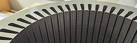
Among the most important arguments of laser cutting is the precision and quality of the laser parts. Using the appropriate cutting gases, the precise laser beam guidance, the high power density and a high cutting speed enable highly precise contour accuracies of ± 0.01 mm, exact, almost right-angled cut edges and clean cut surfaces.
Depending on the material thickness, narrow cut gaps (kerf) of 0.03 mm are also possible. Unlike competing cutting processes, laser cutting does not involve contact between the cutting tool and the workpiece. The laser beam processes the material without contact and with a low thermal load.
In addition, laser cutting is characterized by excellent quality of the workpieces produced. The laser beam of the laser cutting systems is focused so strongly that the kerf is only slightly larger than the laser beam itself. This allows the finest geometries to be produced and duplicated with tolerances of ± 0.1 millimeter. The cutting edges are so clean during laser cutting that post-processing is often not necessary.
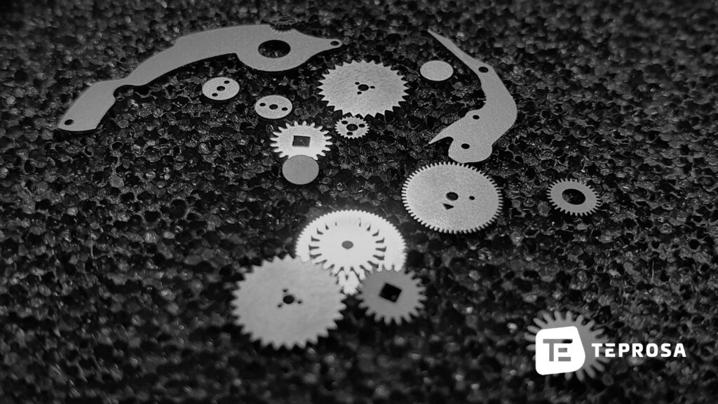
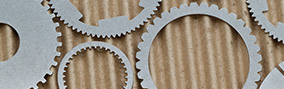
Another advantage of the technology is its versatility. Laser cutting represents a high-tech tool for precisely cutting through sheet steel and metal (light and heavy), ceramics, plastics, textiles and even for many fiber composites. No other cutting process can be used so effectively and easily on so many materials.
Moreover, many laser cutting systems are capable not only of pure cutting, but also laser drilling and engraving. So with one setup process, different processes can be performed to machine a laser part by combining the processes. This increases precision and cost-effectiveness and reduces the probability of errors due to multiple setups and alignments.
Laser cutting can also excel in economics. Due to the high cutting speeds and small kerf, sheets can be processed quickly and efficiently with laser cutting. A comparable material utilization is not achieved with any other process.
In addition, laser cutting requires no tools, which not only results in low setup and wear costs. Another decisive advantage is also that geometries can be changed and adapted at short notice at any time. Thanks to the simple transfer of job data to the laser machine, a job can be started within a very short time after commissioning and with very low setup costs.
Since laser parts usually have very clean and virtually burr-free cut edges, costly and time-consuming post-processing is not necessary in many cases.
With modern laser systems, sheets of several meters in length and width can be processed. At TEPROSA, the focus is more on processing smaller to medium-sized filigree components. We can process sheets with maximum dimensions of 1.0 m x 1.5 m. In terms of material thickness, we are able to cut sheets up to 8 mm thick, depending on the material.
The strong focusing of the laser beam enables minimal kerfs of up to 0.03 mm with a spot diameter of also 0.03 mm. The repeat accuracy of our laser systems is ±2µm. At cutting speeds of up to 50 mm/s, we achieve a contour accuracy of ± 0.01 mm with cutting gas support (oxygen, nitrogen, compressed air).
Our manufacturing conditions for common materials are:
Laser cutting is a cutting process that completely eliminates tooling costs. This fact alone, makes it often cheaper compared to competing processes. But how expensive is laser cutting really? We have compiled the most important cost factors for cutting with a fiber laser.
If you already have the cost drivers in mind during the design of the laser parts, you can increase the cost-effectiveness of production enormously. We reveal how!
In the following, we want to look at the individual factors for the subsequent price of the laser parts once in detail.
| The material | There are many different materials that are suitable for laser cutting. At the same time, the different materials are also sometimes far apart in terms of price. The selection of a suitable material is not always easy, but in terms of the use and cost of the laser part crucial. |
| The material thickness/material thickness | In addition to the cutting speed, the material thickness also determines the time required for the laser beam to penetrate the material. Two factors that significantly affect the price. |
| The cutting speed/feed rate | Depending on the material and how thick the material to be cut is, the laser can operate at a limited cutting speed. Slow speeds automatically imply a longer manufacturing time and lead to higher costs. |
| The cutting length | The length of the outer contour of a cut part results in the cut length, i.e. the travel distance the laser has to cover to manufacture a part. Thus, the cut length is partly responsible for the manufacturing time. |
| The part area | The part area conditions the material consumption. For particularly unfavorable contours (eg circles), the waste can be optimized only conditionally. |
| The cutting accuracy | Generally, higher accuracies require a lower cutting speed. If a higher accuracy of the laser parts is required, the feed rate with which the laser system operates must therefore be reduced. |
| The complexity of the part | The complexity of a component often has a negative impact on several of the above-mentioned factors at once. For example, a contour with a lot of detail and tight curves can mean that the laser has to brake repeatedly and thus only reaches its maximum speed over a small part of the travel path. A large number of necessary recesses, e.g. in components with many holes, also increases the processing time. Also a large number of necessary punctures, for example, for components with many holes increases the processing time. |
To determine the cutting costs of a laser part, the so-called machine hourly rate is used as the basis for calculation. Different machines have different machine hourly rates due to different acquisition and operating costs. To calculate the price of the laser part, the following parameters are considered:
| Material costs | What does the sheet metal cost to purchase? How often is it used for manufacturing? How much wastage occurs with optimal placement? |
| Machine hourly rate | What is the cost of the machine in use per hour? |
| Personnel hourly rate | How much manual effort (e.g. set-up costs, rework, etc.) is required to produce the cutting part? |
| Overhead costs | What are the overhead costs that are not directly involved in the production of the laser part, but must be allocated to manufacturing? |
| Setup costs | How much effort is required to prepare the machine for manufacturing the laser part? How many parts will be manufactured? In the case of single-part production, the proportional setup costs are the highest; in the case of large series orders, they are vanishingly small. |
| No tooling costs | Unlike punching or milling, for example, no tool is required for laser cutting. The laser beam as the “sole tool” can be used for any individual component. Investment and maintenance costs for tools are therefore saved completely. This financial advantage, the competing processes often can no longer catch up. |
As explained earlier,high component complexity quickly leads to high cutting times and therefore high prices. Where complexity is needed, however, this fact cannot be ignored, of course.
The situation is often quite different with general manufacturing tolerances and technical requirements for laser cuts. Here, an inaccurate specification or an exaggerated design drawing can quickly increase the cost of laser cutting unnecessarily.
Now that you’ve learned all about how laser cutting equipment works and the process of laser cutting, you can get started right away with your online inquiry for laser parts at TEPROSA. Use our online inquiry form to place your request at any time through our website without any additional effort. Simply upload your manufacturing data to our server and deposit the material(s) you require.

TEPROSA GmbH, Paul-Ecke-Strasse 6, 39114 Magdeburg, Germany
Geschäftsführer & Gesellschafter der TEPROSA GmbH.
Paul-Ecke-Str. 6
39114 Magdeburg
Deutschland


